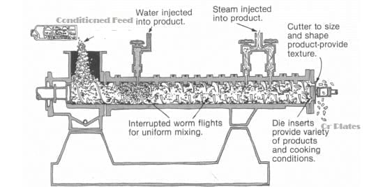
The “I.F.” Extruder-Cooker
The Extruder-Cooker consists internally of a discontinuos screw turning within a retaining tube, fitted with breaker bolts, which match the interruption of the screw. The Screw, when viewed from the drive end, turns in a counter clockwise direction and is driven through an enclosed gearcase or thrust unit.
The “I.F.” Extruder is fitted with a variable feeding device of such size and range as to permit adequate feed rate changes to the Extruder, as are indicated during processing. Between the metering screw and the Extruder inlet, is a feeder screw, which turns at a constant rate sufficient to maintain a fast, uniform, low level feed to the
Extruder downspout.
Positioned at the Extruder discharge is a cutter assembly for the purpose of cutting the discharging material into uniform and easily handled lengths.
Water is added to the incoming dry mix material through a water line equipped with a pressure regulating valve and flowmeter, which terminates at a special water injection valve located in the Extruder tube. The water produces a moisture level in the dry mix suitable for conversion of the starch.
Sparge streams is added to the moistened material through a combination of special steam injection valves located in the Extruder tube. This steam produces a temperature increase in the material sufficient to cause the starch conversion and provides the expansive medium necessary to produce a product of low bulk density. In providing this heat, condensate is formed, which is taken into consideration when process water rates are established.

The Extruder Motor is electrically interlocked with the feeder screw and the metering screw motors, so that the Extruder must be started first and will shut down the feeder screw and metering screws motors if it inadvertently stopped during operation. In addition, the equipment is inter-controlled by a current sensative relay which will, at a preset condition is Extruder motor load, stop the feeder screw motor, the metering screw motor and the water addition, through the action of a solenoid valve located in the water line. All functions will automatically restart when the Extruder motor load decreases. This Extruder motor load-limiting device can be set for a range of tip values. Normally the tip value is about 90 of the applied motor full load current ratings. The wiring circuit is such that the relay will automatically restart controlled equipment at 88 of the tip-out value. This provides automatic protection of the Extruder in the event of a malfunction in the water, feed or steam systems.
A bulk density in the extruded and expanded material of 16 pounds per cubic foot and up may be produced, depending upon the formula employed. It is the primary factor on which the extrusion/expansion operation is judged. Extruder/Expanded materials as it discharges from the Extruder, will have moisture content of from 20 to 28. A drying operation follows which lowers the moisture to from 10 to 12, or less, to produce a material ideal for subsequent cracking and storage.
The drive for the Extruder-Cooker is a V-Belt type and the Extruder uses grease-lubricated bearings, which require only minor periodic service.