Hammermills and Roller Mills
Published: July 17, 2020
Source : Kim B. Koch, Ph.D. / Northern Crops Institute - North Dakota State University Feed Center Manager.
Summary
The advantages and disadvantages of hammermills and roller mills are considered. The modes of action involved in particle size reduction for each mill are discussed.
Ingredients come to the feed processor from a variety of sources. Many of these, particularly the coarse cereal grains, require some degree of processing before they are ready to be blended into an animal ration. The process of particle size reduction improves ingredient performance during mixing and, in most cases, the nutritive value of an ingredient can be improved or more nearly realized.
There are many ways to reduce the particle size of feed ingredients. Two of the most common pieces of equipment used are the hammermill and the roller mill. The choice of which to use depends upon the unique requirements of every individual situation. Either piece of equipment is capable of producing what is often termed in the industry as a “satisfactory grind.” However, excessive size reduction can result in wasted electrical energy, unnecessary wear on mechanical equipment, and possible digestive problems in livestock and poultry.
The information provided in this bulletin will help feed processors decide which mill (roller or hammer) is best suited for their grinding needs. This bulletin also contains information pertaining to the general design and operating parameters of roller mills and hammermills, and an explanation of how these mills reduce ingredient particle size.
Size Reduction
The initial reduction of cereal grains begins by disrupting the outer protective layer of the seed (hull), exposing the interior (Figure 1). Continued size reduction increases both the number of particles and the amount of surface area per unit of volume. It is this increased surface area that is of primary importance. A greater portion of the grain’s interior is exposed to digestive enzymes, allowing increased access to nutritional components such as starch and protein. The enhanced breakdown of these nutritional components improves absorption in the digestive tract. The overall effect is increased animal performance (MF-2050). Size reduction is also used to modify the physical characteristics of ingredients resulting in improved mixing, pelleting, and, in some instances, handling or transport.
Hammermills accomplish size reduction by impacting a slow moving target, such as a cereal grain, with a rapidly moving hammer. The target has little or no momentum (low kinetic energy), whereas the hammer tip is travelling at a minimum of 16,000 feet per minute (4,880 m/min) and perhaps in excess of 23,000 feet per minute (7,015 m/min) (high kinetic energy). The transfer of energy that results from this collision fractures the grain into many pieces. Sizing is a function of hammer-tip speed; hammer design and placement; screen design and hole size; and whether or not air assist is used.
Because impact is the primary force used in a hammermill to reduce particle size, anything that: increases the chance of a collision between a hammer and a target, increases the magnitude of the collision, or improves material take-away, would be advantageous to particle size reduction. The magnitude of the collisions can be escalated by increasing the speed of the hammers. Anderson (1994) stated that when drive speed and screen size were kept constant, the increased hammer-tip speed obtained from increased rotor diameter produced particles of smaller mean geometric size.
Particles produced using a hammermill will generally be spherical in shape with a surface that appears polished. The distribution of particle sizes will vary widely around the geometric mean such that there will be some large-sized and many small-sized particles.
Roller mills accomplish size reduction through a combination of forces and design features. If the rolls rotate at the same speed, compression is the primary force used. If the rolls rotate at different speeds, shearing and compression are the primary forces used. If the rolls are grooved, a tearing or grinding component is introduced. Coarse grooves provide less size reduction than fine grooves do.

There is little noise or dust pollution associated with properly designed and maintained roller mills. Their slower operating speeds do not generate heat, and there is very little moisture loss.
Particles produced tend to be uniform in size; that is, very little fine material is generated. The shape of the particles tends to be irregular, more cubic or rectangular than spherical. The irregular shape of the particles means they do not pack as well. For similar-sized particles, bulk density of material ground on a roller mill will be about 5 to 15 percent less than material ground by a hammermill.
Hammermills
Advantages:
- produce a wide range of particle sizes
- work with any friable material and fiber
- less initial purchase cost compared to roller mills
- offer minimal expense for maintenance
- generally feature uncomplicated operation
Disadvantages:
- provide less efficient use of energy compared to the roller mill
- may generate heat (source of energy loss)
- may create noise and dust pollution
- produce greater particle size variability (less uniform)
General Design
The major components of these hammermills, shown in Figure 2, include the following:
- a delivery device to introduce material into the path of the hammers; a rotor comprised of a series of machined disks mounted on the horizontal shaft
- free-swinging hammers that are suspended from rods running parallel to the shaft and through the rotor disks
- a perforated screen and either gravity- or air-assisted removal of ground product
Feeder Design
Material is introduced into the paths of the hammers by a variable speed vein feeder. This type of feeder can have its motor slaved by a programmable controller to the main drive motor of the hammermill. The operational speed of the feeder is controlled to maintain optimum amperage loading of the main motor.
Hammer Design
The design and placement of hammers is determined by operating parameters such as rotor speed, motor horsepower, and open area in the screen. Optimal hammer design and placement will provide maximum contact with the feed ingredient.
Mills in which the rotor speed is approximately 1,800 rpm, hammers should be about 10 inches (≈ 25 cm) long, 2.5 inches (≈ 6.35 cm) across, and 0.25 inches (≈ 6.4 mm) thick. For a rotor speed about 3,600 rpm, hammers should be 6 to 8 inches (≈ 15 to 20 cm) long, 2 inches (≈ 5 cm) across, and 0.25 inches (≈ 6.4 mm) thick. The number of hammers used for 1,800 rpm should be 1 for every 2.5 to 3.5 horsepower, and for 3,600 rpm, one for every 1 to 2 horsepower. Hammers should be balanced and arranged on the rods so that they do not trail one another. The distance between hammer and screen should be 0.5 inches (≈ 12 to 14 mm) for size reduction of cereal grains.

The velocity or tip speed of the hammers is critical for proper size reduction. Tip speed is calculated by multiplying the rotational speed of the drive source (shaft rpm) by the circumference of the hammer tip arc (Formula 1).

Tip speeds commonly range between 16,000 and 23,000 feet per minute (5,000 and 7,000 m/min). When tip speeds exceed 23,000 feet per minute, careful consideration must be given to the design of the hammermill, the materials used in its construction, and the fabrication of all the components. Simply changing the rotational speed of the drive source is not a recommended method of increasing hammer speed in excess of 23,000 feet per minute.
Screen Design
The amount of open area in a hammermill screen determines the particle size and grinding efficiency. The screen must be designed to maintain its integrity and provide the greatest amount of open area. Screen openings (holes) that are aligned in a 60-degree staggered pattern optimize open area while maintaining screen strength. This method will result in a 40 percent open area using 1 /8 inch (3.2 mm) holes aligned on 3 /16 inch (4.8 mm) centers.
The reader is urged to pay particular attention to the ratio of open screen area to horsepower. Recommended ratio for grains would be 8 to 9 square inch (≈ 55 cm2 ) per horsepower (Bliss, 1990). Not enough open area per horsepower results in the generation of heat. When the heat generated exceeds 120°F to 125°F (44°C to 46°C) capacity may be decreased as much as 50 percent.
The removal of sized material from a hammermill is a critical design feature. Proper take-away affects not only the efficiency of operation, but also particle size. When the correct ratio of screen area to horsepower is used and proper distance between hammers and screen face is maintained, most of the correctly sized particles will exit the screen in a timely manner.
Anderson (1994) stated the particles that do not pass through the screen holes become part of a fluidized bed of material swept along the face of the screen by the highspeed rotation of the hammers. As these particles rub against the screen and each other their size is continually reduced by attrition. This excessive size reduction is counterproductive. Energy is wasted in the production of heat, throughput is restricted, and particles become too small.
Most newer hammermills are equipped with an airassist system that draws air into the hammermill with the product to be ground. Systems are designed to provide reduced pressure on the exit side of the screen to disrupt the fluidized bed of material on the face of the screen, thus allowing particles to exit through screen holes. Some fullcircle hammermills are designed so the screen is in two pieces. It is possible to use a larger hole size on the upward arc of the hammers to further reduce the amount of material on the face of the screen.
Roller mills
Advantages:
- energy efficient
- uniform particle-size distribution
- little noise and dust generation
Disadvantages:
- little or no effect on fiber
- particles tend to be irregular in shape and dimension
- may have high initial cost (depends on system design)
- when required, maintenance can be expensive
General Design
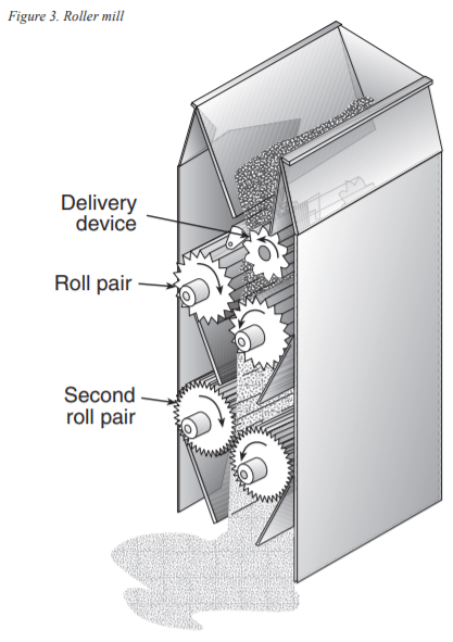
There are many manufacturers of roller mills, but they all share the following design features shown in Figure 3:
- a delivery device to supply a constant and uniform amount of the material to be ground
- a pair of rolls mounted horizontally in a rigid frame
- one roll is fixed in position and the other can be moved closer to or further from the fixed roll
- the rolls counter rotate either at the same speed or one may rotate faster; roll surface may be smooth or have various grooves or corrugations
- pairs of rolls may be placed on top of one another in a frame.
To ensure optimum operation, material must be introduced between the rolls in a uniform and constant manner. The simplest feeder is a bin hopper with an agitator located inside it and a manually set discharge gate. This type of feeder is best suited for coarse processing. For grinding operations, a roll feeder is suggested. In this type of feeder, the roll is located below the bin hopper and has a manually set or automatic adjustable discharge gate. If the gate is adjusted automatically, it will be slaved to the amperage load of the main motor of the roller mill.
The rolls that make up a pair will be 9 to 12 inches (23 to 30.5 cm) in diameter, and their ratio of length to diameter can be as great as 4:1. It is very important to maintain the alignment between the roll pairs. Sizing of the material is dependent upon the gap between the rolls along their length. If this gap is not uniform, mill performance will suffer, leading to increased maintenance costs, reduced throughput, and overall increased operation costs. The gap may be adjusted manually or automatically through the use of pneumatic or hydraulic cylinders operated through a computer or programmable controller.
Each pair of rolls is counter rotating. For improved size reduction one of the rolls rotates faster. This results in a differential in speed between the roll pair. Typical differentials range from 1.2:1 to 2.0:1 (fast to slow). Typical roll speeds would be 1,300 feet per minute (≈ 395 m/min) for a 9-inch (≈ 23 cm) roll to 3,140 feet per minute (≈ 957 m/min) for a 12-inch (≈ 30.5 cm) roll. Usually a single motor is used to power a two high roll pair, with either belt or chain reduction supplying the differential. In a three high roll pair, the bottom pair will have a separate drive motor. In addition, the roll faces can be grooved to further take advantage of the speed differential and improve size reduction.
By placing (stacking) pairs of rolls on top of one another, two or three high, it is possible to reduce particle sizes down to 500 microns, duplicating the size-reducing capability of a hammermill for grain. For coarse reduction of grain, a roller mill may have a significant advantage (perhaps as high as 85 percent) over a hammermill in terms of throughput/kwh of energy. For cereal grains processed to typical sizes (600 to 900 microns) for the feed industry, the advantage is about 30 to 50 percent. This translates into reduced operating expense.
This article was originally published in Kansas State University Agricultural Experiment Station and Cooperative Extension Service, MF-2048
Anderson, S. 1994. Large Rotor High Speed Hammermills: Beyond Screen Size. Feed Management, Vol. 45, No. 9, 20-22.
Bliss, B. 1990. Hammermilling Technology. Bliss Industries, Inc., Ponca City, OK.
Goodband, Robert, Mike Tokach, and Jim Nelssen. 1995. The effects of diet particle size on animal performance. Cooperative Extension Service, MF-2050. Kansas State University, Manhattan.
Related topics:
Authors:

North Dakota State University
Recommend
Comment
Share

Would you like to discuss another topic? Create a new post to engage with experts in the community.


Featured users in Animal Feed


